Products & Services
- • Bus duct products & Services
- • Switchgear Products
- • Disconnect Switch
- • Crown-sulator ®
- • Joule-ious 105
- • Field Services
Bus duct products & Services
• Iso Phase Bus Cooler – Nuclear Plant
Please click on image for a hi res version.
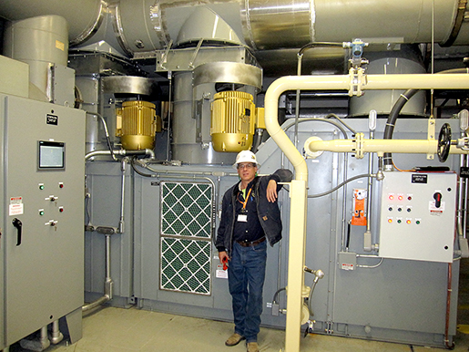
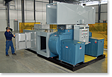
Crown Electric: Engineers – Designs – Fabricates and Installs IPB Cooling Packages for new - retrofit and upgrade applications.
Forced CoolingOnce voltage clearances are accounted for, the physical size of Isolated Phase Bus housing and conductor is largely dictated by the system's continuous current rating and the maximum allowable temperature rise of the bus above the specified ambient temperature.
As the conductor current increases, it is necessary to dissipate the associated I2R heat loss generated to keep the bus within its allowable thermal rise. To limit the temperature rise to acceptable specified levels, it is necessary to either increase the physical size of the conductor and enclosure, or to actively dissipate the heat with some method of cooling.
Over the years, several methods of cooling have been investigated and under most circumstances the decidedly practical and economical method of actively dissipating the excess heat is the use of a closed forced air cooling system.
Forced Cooled System
In a forced air system, air is channeled down the IPB housings in either the center or the outer two phases. Upon reaching the ends of the bus assembly, (at the generator and transformer ends), the air returns through the non-introduced phase(s). Except on very short bus runs, the heat exchanger is usually located as close as possible to the center of the linear bus run. The air flows from the heat exchanger towards both the transformer and generator. As the warm air flows out of the return phase(s) into the heat exchanger, it is dispersed by an equalizing baffle, then passed on to the cooling coils. The air then passes through a water eliminator before re-entering the enclosure(s) to be re-circulated.
Crown Electric's high efficiency, twin centrifugal fans feature in-line air flow. This arrangement provides either 50% or 100% backup cooling availability.
Monitoring, indication and alarm devices are available. The most common alarms indicate failure of air circulation in the bus and restrictions of water flow in the cooling coils.
In the event the forced air from one phase becomes ionized and then passes into another phase, the insulation integrity of the air between the conductor and the grounded enclosure can be reduced. This condition is alleviated by providing interphase de-ionizing baffles. The air plenums surrounding the de-ionizing baffles will often include regulators to adjust the air flow so that temperature balance can be managed due to unequal air paths and air velocities throughout the IPB system.
The retuning warm air flows out of the returning phase(s) and into the air to water heat exchanger where BTU's and moisture are removed and the process continues.


